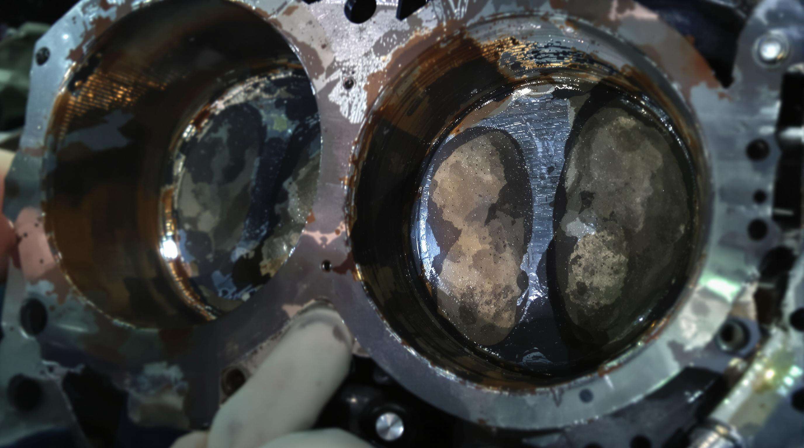
It is important to identify cylinder liner wear patterns to prevent engine failure and to extend service life. Unique wear patterns show what's missing: an elliptical progressive wear pattern usually means there are constant side forces, and localized scoring can sometimes reveal fluid failure. Industry research demonstrates that engines overextended beyond maintenance intervals experience wear rates of up to 0.15mm/1000 hours, which drastically shortens the life of the engine. Early recognition of the pattern enables a focused management before irreparable organs damage.
Scuffing is evident under a scanning electron microscope to consist of lumps and irregular patches of micro-welded material, resulting from the lack of lubrication when piston rings are slung close against liner wall, and metal-to-metal friction causes them to adhere and tear material from the liner. This results in very visible long straight scratches, and then sometimes a bluish tint if it got too hot. Thermal distortion results in a distortion of the liner shaped like an hourglass, caused by local cooling flow obstructions, when the temperature differences there are more than 180°F. Foundations for this ProofThe signs of the problem are spikes in oil consumption above 1.5% of the fuel use rate, and noisy piston slap at cold starts.
Precision measurement requires taking micrometer readings at multiple cross-sections following standardized matrices:
| Measurement Position | Acceptable Out-of-Roundness | Maximum Diameter Expansion |
|---|---|---|
| Top Dead Center | ✓0.03mm | ✓0.1% of nominal diameter |
| Mid-Stroke | ✓0.05mm | ✓0.15% of nominal diameter |
| Bottom Dead Center | ✓0.04mm | ✓0.12% of nominal diameter |
Operators typically detect expansion by noting longitudinal stretch marks while ovality appears as irregular contact patterns on piston skirts. Consistent deviations beyond factory tolerances necessitate immediate liner replacement to maintain compression integrity.
Proper cylinder liner replacement requires specialized tools and systematic preparation to ensure precision and prevent engine damage. Industrial-grade puller systems and calibrated hydraulic presses form the foundation of safe removal, while comprehensive safety protocols protect technicians and maintain workspace integrity during this critical maintenance operation.
Due to the high tensile strength of engine block materials, mechanical or hydraulic puller arrangements with ¥10T extraction force are necessary to expel seized liner without distortion of engine block. Couple these liners with press systems that have adjustable pressure controls (50–200 MPa range) for different liner sizes and materials. Precision Measurement Tools (e.g., Digital Bore Gauges, Dial Indicators) check cavity dimension + or - 0.01 mm before installing, reducing field rework risk by 32%.
Technicians must wear OSHA-compliant PPE, including heat-resistant gloves, ANSI Z87-rated eye protection, and forced-air respirators when handling deteriorated liners. Prepare the workspace by:
This setup reduces procedural errors by 40% compared to ad-hoc environments. Always maintain emergency shutdown controls within arm’s reach during hydraulic press operations.
The first steps should be draining engine oil, coolant and fuel to avoid any spillage. Systematically disassemble the cylinder head, pistons, and connecting rods, making sure to tag items to be reassembled. Engines that are prepared with structured disassembly procedures have a 40% decrease in installation failures. Keep your work area clean to help prevent debris of any kind from getting in, and, whenever these are sharp-edged parts, like piston rings, or gasket debris, use some cut resistant gloves.
In Dry liners, the engine block is heated up to 120-150°C(250-300°F) to ease the process of removal, whereas in wet liners hydraulic pullers are used to overcome the pumping out resistance which is the resistance offered by sealing rings. 62% decrease in block scoring events with the dry method compares to the wet method. Be sure to first check liner type from OEM technical literature before choosing your tools—applying a wet-style puller to a dry liner can crack the block’s counterbore.
Keep the puller tools perpendicular to the liner walls to avoid un-even stress distribution. For hard liners, oscillate ±5° rotating and apply consistent hydraulic pressure (max 15 kN). After extraction, visually check the block for microcracks via dye penetrant. Preventable Block Damage 78% of preventable block damage is due to thermal distortion allow to cool to room temperature before comparing bore dimensions to factory specifications.
Correct block preparation should start by removing all of the debris with steam cleaning or plastic bead blast to remove the oil and carbon deposits. These are followed by solvent cleaning to remove microscopic impurities -- a requirement to avoid premature sizing failure. Maintenance analysis showed that cleaning surfaces for liners was inadequate in 28% of the torn seals.
Inspect the block for cracks or warping using magnetic particle testing or dye penetrant methods. Resurface flange seating areas exceeding 0.05 mm distortion, and deburr edges to minimize stress concentrations. These steps ensure uniform pressure distribution during liner installation.
Post-cleaning, validate critical dimensions against manufacturer specifications:
| Parameter | OEM Specification | Typical Tolerance Range |
|---|---|---|
| Bore Diameter | Measured ±0.02 mm | 0.01–0.03 mm |
| Counterbore Flatness | <0.04 mm | 0.03–0.05 mm |
| Liner Protrusion | 0.10–0.15 mm | ±0.02 mm |
| Surface Roughness (Ra) | 1.6–3.2 µm | Not to exceed 4.0 µm |
Use dial indicators to check counterbore alignment and verify flange seating surfaces meet roughness targets. Non-compliant dimensions risk improper sealing, thermal hotspots, and reduced engine lifespan. Adherence to OEM guidelines ensures optimal liner performance under operational stresses.
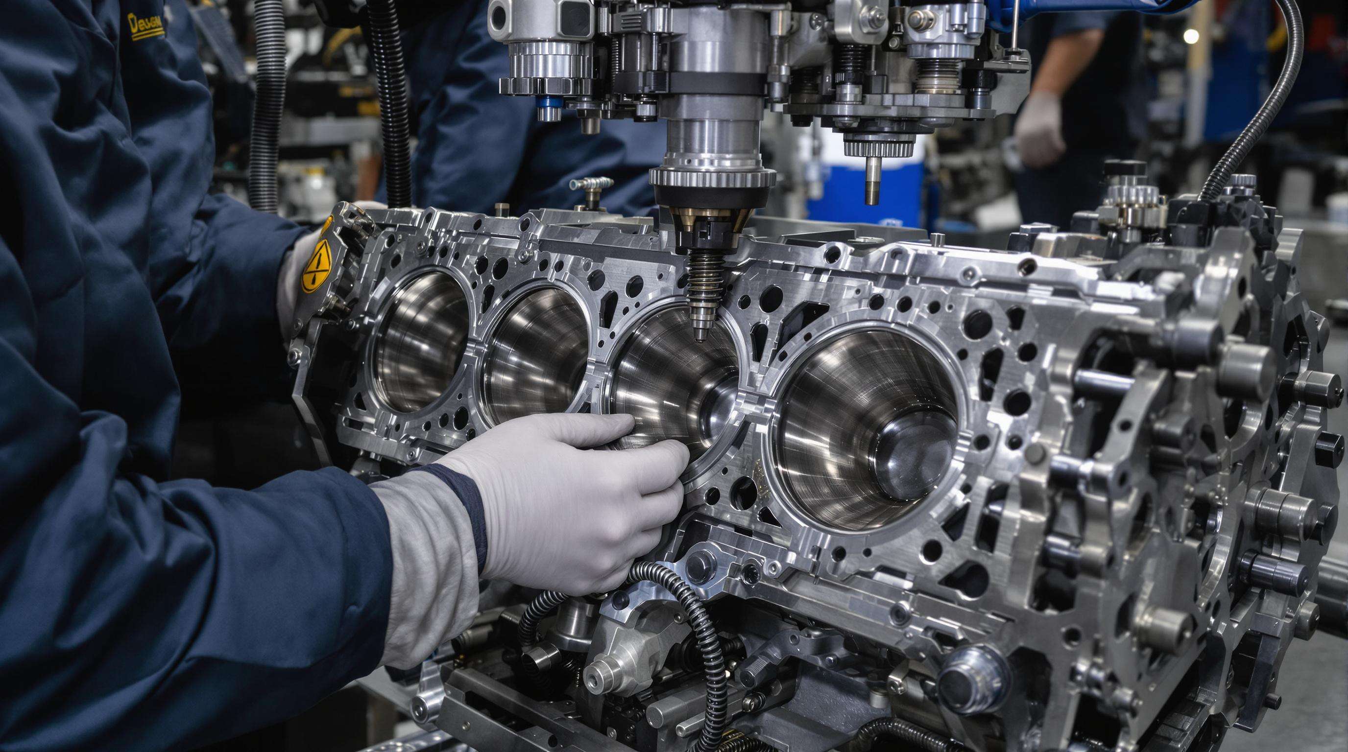
Correct installation avoids premature failure and improves engine performance. This is the basis of accurate press-fit tolerances calculations and thermal strategies to manage the system. Cylinder liner changes require very precise following of O.E.M. specifications—a 0.001” deviation in fit tolerance reduces the service life by 17%. Three vital stages ensure the process is successful: press-fitting mechanics; verification of protrusion; and temperature conditioning on curing.
The interference fit, depending on the type of liner, will generally weigh in the range of 0.002” to 0.005” over the cylinder bore diameter. Pre-compute temperature differences: Cool dry liners to -20°C and heat the block to 150°C to help facilitate insertion. Only use manufacturer-approved lubricants on O-ring grooves – not the outside of the liner. Utilize hydraulic press applying uniform radial pressure less than 250 PSI to prevent deformation. Sudden installation raises risks of micro-cracks by 40% each engine dynamometer tests.
Post-installation liner protrusion shall read within 0.003”-0.006” tolerance and throughout all the cylinders measured using dial comparators. 72% of head gasket failures is result of uneven protrusion. Use shims to make final adjustments before caps are torqued. At the same time, check cooling jacket clearancesan inproperly squared jacket eliminates 30% of heat dissipation. Verify annular space with OE thickneapply feeler gauges in the OE thickness from OE places, even gap of 0.015” around coolant passages.
Do not test for hydraulic pressure until after full 24-hour cure to stabilize seals and resins. Step-up engine temperatures during first run - Ramp from 700rpm to 3500rpm over 90 minutes. Supervise thermal growth isotherms between sleeves materials and parent blocs; aluminum blocs growth 3× faster than iron blocks, increase expansion and distortion in play. Get closer to a true locking angle by stabilizing at operating temperature for accurate mating surface contact. Post cure checks bore distortion 0.00025 “ per standardised OEM run-in method.
Starting of the engine after the replacement of cylinder liner calls for controlled break-in to achieve adequate running in between the piston rings and new liners. With different RPM for the first 50 running hours, gradually add load to the peak level. OEM mandated thermal cycling procedures virtually eliminate glazing and guarantee even contact surfaces. This incrementally lessens early wear by 43% and provides ideal compression seals based on engine makers' requirements.
Perform coolant pressure test right after break-in to check liner seal leakage, jacket and head-gasket sealing. Use of chemistry and cylinder leak-down testing to evaluate sealing integrity of a combustion event in which <10% pressure loss is considered satisfactory. Confirm through thermo-images of liner surfaces at high rate the heat dissipated while in operation. The true acid test is 30 minutes minimum at full load with monitoring for coolant contamination and exhaust emissions, only then, will the managerial decision to return equipment to normal service cycles happen.
Scuffing in cylinder liners is caused by a lack of lubrication, resulting in metal-to-metal contact that causes the rings and liner to adhere and tear material, leading to long straight scratches.
Thermal distortion can be identified by an hourglass shape of the liner, caused by local cooling obstructions and high-temperature differences. Signs include spikes in oil consumption and noisy piston slaps at cold starts.
Acceptable measurements include out-of-roundness limits (e.g., Top Dead Center: ≤0.03mm) and maximum diameter expansion (e.g., ≤0.1% of nominal diameter at Top Dead Center).
Dry liners involve heating the engine block to ease removal, while wet liners use hydraulic pullers. Each method requires careful application to avoid block damage.
Precautions include ensuring correct press-fit tolerances, measuring liner protrusion accurately, and following appropriate cooling jacket alignment for effective installation.
 EN
EN